ICP CONNECTION UNDER-TRACK INSTALLATION AT WESTON-SUPER-MARE
Western Power Distribution
Enable Infrastructure’s civils team, Enable Power Systems team, and Enable Design was assigned by Western Power Distribution (WPD) to carry out the installation of under-track crossings (UTX) for new cables in Weston-Super-Mare. The project required the cables to connect the feeder grid to two separate substations, one located at Warne Road and the other at Bourneville Road playing fields in the North Somerset town. Continuous track monitoring was necessary throughout the project due to Enable Infrastructure working under an operational railway with the project being broken down into its component assets, allowing for focused work on manageable scopes.
The project
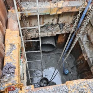
Excavation process was initiated following the marking of shaft pit locations by our setting engineer in accordance with the AFC design and the permit approval, utilizing a dig-and-push technique to create a 3.4m-deep drive pit (4m x 4m) and a 2m x 2m reception pit, both with a depth of 3.4m.
In order to accommodate the guided auger-boring equipment, reinforced concrete thrust walls were constructed in the drive pits, with two sides measuring 300mm thick and the other two sides measuring 500mm thick. The construction of formwork walls involved the use of shuttering ply, timbers, and reinforcement A393 mesh. Once the concrete was poured into the formwork, the walls underwent testing to ensure that they had achieved the required strength as per the design specifications.
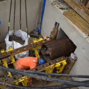
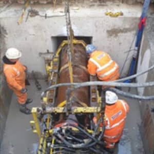
Following confirmation of the bore’s set-out and mark line gradient by Enable Design engineers, as well as the signing of the drilling permit, the auguring process commenced. This involved using a sacrificial steel sleeve, which was connected through welding of additional sections. The sleeve, flight auger, and cutting head were loaded onto a 13t machine and lowered under the supervision of a qualified slinger signaller and banksman. The cutting head was attached to the rear of the pilot rod, while the flight auger was connected to the drive of the auger machine.
We began Boring with the auger being filled, and as the sacrificial steel sleeve was pushed into the ground, the flight augers were simultaneously rotated. The flight augers were then retracted to the drive shaft, clearing any loose spoil that remained inside the sleeve. Each section of the flight auger was disconnected and lifted to the surface as it arrived in the drive shaft. The spoil from the augers was discharged into the drive shaft, loaded into skips, and removed from the pits using the 13t machine. The spoil removal process was closely monitored to assess its correspondence to the volume of the installed sleeve, with an expected increase of approximately 15-20% after accounting for bulking. Upon completion of the auger-boring, the auger machine master frame and ancillary items were removed.
The challenge
- The office space was situated in a park, next to a football field, and close to drainage rhynes. One particular obstacle we faced was the presence of protected trees in the route protection zone (near the drive pit on the playing field), requiring us to take careful steps to comply with environmental regulations.
- Balancing the sometimes-conflicting demands of WPD and Network Rail can be challenging, particularly when it comes to maintaining the functionality of the railway while operating within live substations.
The solution
Prior to finalizing the contract, we formulated an extensive Environmental Management Plan that encompassed collaborating with the local governing body to devise a strategy and blueprint for safeguarding the trees. This entailed creating exclusion zones and implementing a route protection plan to ensure the trees’ preservation. To overcome the second obstacle, we initiated constructive discussions among all stakeholders to ensure a comprehensive comprehension of the project’s requirements. Once a mutual understanding was reached, our proficient Enable Design team devised a customized plan that satisfied all parties involved.
The deliverables
- Two under-track crossings
- 610mm sleeve auger
- Two 2m x 2m x 3.4m reception pits
- Two 4m x 4m x 3.4m drive (thrust) pits
- Reinforced concrete retaining walls
- Reinforced concrete floors
- Temporary works
- Sheet piles
- Formwork
- Resurfacing – Tarmac/concrete
- White-lining
- Reinstatement of a play park and football pitch
- Installation of UTX signage
- Ducts: 4 x 150mm & 3 x 100mm
- Steel casings (32m at Bourneville & 28m at Warne Rd)
Gallery


“Enable Infrastructure worked to the high standards set by WPD. Despite on-site challenges, they met the deadlines given to them, sticking to their programme of works. The works were completed safely and on time. I would have no hesitation in using Enable Infrastructure in the future.” - Gary Beasley, Western Power Distribution project engineer
Your Trusted Partner for Infrastructure Excellence
Whether you’re upgrading critical rail networks, improving highways, delivering essential utilities, or developing energy connections and power systems, Enable Infrastructure is your trusted partner for success.
Join us in our mission to deliver innovative, on-time, and on-budget infrastructure solutions that shape the future. Together, we push boundaries and deliver outstanding results across rail, energy, utilities, and highways sectors.
Discover how our award-winning expertise can help you navigate complex projects with confidence.
Get in Touch